
What is a Current Sense Resistor: how is it used for measurements
Current sense resistors are an ideal way or measuring current in many circuits, but it is necessary to understand all the trade-offs to achieve the best results.
Measurement Techniques Includes:
Current sense resistors
Current transformers & measurement applications
The most obvious method of making a current measurement is to break the circuit and have and have the sensor or measurement device in series in the circuit.
This is not always convenient or practicable and often the use of a current sense resistor is a far better option enabling the current measurements to be made without the need to unduly affect the circuit.
When using a current sense resistor, there are a number of concepts and precautions that need to be observed.
Generally current sense resistors are low value, and dependent upon the circuit they may need to be high power rated resistors.
The current sense resistors may also be incorporated into the actual electrical or electronic circuit design so that readings can be taken occasionally or as part of an inbuilt monitoring system that may be an integral part of the operation of the circuit.
Having a current sense resistor built into an electronic circuit design may require a few more electronic components to be used, but there can be cost savings in terms of the functionality provided, etc.
Basic concept of current sense resistors
The traditional method of measuring current is to put a current meter in a circuit and use this to measure the current flowing though it.
This is the most obvious method of measuring current and it has been used for many years - it is the way in which multimeters are designed to measure current.

The disadvantage of this method of measuring current is that the measuring device, typically a digital multimeter needs to actually be in the circuit. Having a multimeter in circuit with all the current flowing through it can also lead to other issues with the circuit as a result of the long leads typically used, especially for high currents or circuits carrying RF.
To overcome these issues when designing an electronic circuit where current needs to be measured or sensed either continuously or regularly, it is far more convenient to measure the current across a sense resistor that is permanently in circuit.
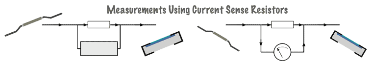
There are two ways of using a permanently in-circuit sense resistor, namely using a series resistor approach and a shunt resistor approach:
• Series resistor:
The series resistor approach requires that all the current passes through the series resistor and then the voltage is measured across the series resistor.
All the current int he circuit flows through the series current sense resistor.

Using a series current sense resistor, a measurement of the voltage across the resistor is made, and this is converted to current knowing the value of the resistor.
Knowing the resistance of the series resistor, and the voltage, it is a simple Ohm's Law calculation to determine the current.
Where:
I = current flowing through the resistor in amps,
V = potential difference in volts across the resistor,
R = Value of the sense resistor on ohms.
This approach to current sensing does not change the circuit conditions when the voltmeter is applied, although the sense resistor itself does. If RF is present the lines to the voltmeter can be isolated to RF using series chokes and resistor and a from the circuit using series chokes and / or resistors and decoupling capacitors can also be employed. These could be built into the actual circuit if required.
The series resistor approach tends to be used more widely in test systems these days because it is easier to measure voltage than current directly and the series current sense resistor technique is easier to employ.
• Shunt resistor:
With the shunt resistor approach to using a current sense resistor, only part of the current flows through the sense resistor, and a known ratio flows through the ammeter, or other form of current sensing circuit. For a shunt resistor, the measurement that needs to be made by the measurement device is that of current.

For this approach to be able to operate satisfactorily, it is necessary to know the resistance of the shunt sensing resistor as well as that of the ammeter. It is then easy to work out the overall current flow. For ease of calculation, the ratio of the resistance of the shunt sensing resistor and the ammeter may be made so that the current flowing through each leg is 10:1 or 100:1, etc.
This approach may mean that there is some change to the circuit operating conditions, although if a sufficiently small proportion of the current flows through the ammeter, then this can be ignored. However the resistance of the ammeter must be accurately known and any decoupling for RF, etc must be built into the circuit and its resistance accommodated within the calculations.
The shunt resistor approach is that which is used inside analogue multimeters. Here different shunt resistors can be switched into the multimeter circuit to give the different ranges.
Both approaches require a resistor to be placed suitably in the circuit so that the current can be measured.
Of the two approaches, the series resistor approach is by far the most widely used because voltage is generally much easier to sense than current.
When designing circuits to use a current sense resistor, its affects must be taken into consideration during the design.
Current sense resistor applications
Resistors to provide current sensing can be used in a wide variety of circuits. They provide a really easy method of measuring current without the need for any disruption of the circuit. The measuring device can simply be placed across the sense resistor and the readings taken.
The applications for current sensing resistors vary from small electronic circuits, including RF circuits, right up to high current applications including electric vehicles.
This approach to current measurement is often used in electric vehicles to monitor the motor current, even applying feedback to ensure the optimum current is applied to the motors.
It can also be used in battery packs, especially lithium ion ones where battery management is key and an account of charge and discharge current needs to be monitored.
It may also be used in general electrical or electronic circuit designs to enable the easy monitoring of the current taken by a circuit for test purposes, or as part of the general operation of the circuit.
Requirements for a current sensing resistor
A current sense resistor is in essence the same as other forms of resistor, although there are a few characteristics that mean that some resistors are manufactured specifically for current sensing.
For most cases a current sense resistor will have a low resistance which is accurately known, and a high current rating and power dissipation so that it can handle the high levels of current that may need to pass through it.
Whatever the applications for the current sensing resistor, the same basic principles apply. These need to be incorporated into the basic electrical or electronic circuit design.
• Resistor value
The value of the resistor needs to be a careful balance. On one hand the resistor usually needs to have a low value so that it has the minimum effect on the circuit. Having a low value also reduces the level of power dissipation, and with some sense resistors being placed in high current paths, this can be a significant issue.
However, if the value is low, then the voltage developed across the resistor is obviously less. This can give rise to some issues in measuring the voltage. Noise can be an issue especially in environments that might have a lot of electrical activity etc.
Resistors intended for current sense applications are generally available at integer milliohm values up to an ohm and then at multiples of 5 milliohms above this, in addition to standard E24 values.
• Tolerance
The tolerance of the resistor is naturally very important. Errors in the value of the current sense resistor will naturally reflect into the accuracy of the reading. For some applications where accuracy is important, resistors with accuracy levels of much better than 1% may be used. For other applications where the accuracy is not so important, 1% may be perfectly adequate.
• Power rating
For soem circuits using current sensing, the power rating may not be a major issue, but in all instances, this should be a real consideration. The power will be equivalent to I2R. So for electrical and electronic designs where high currents are present, the power dissipation capability of the resistor needs to be accommodated.
Many resistors are larger and have the ability for heat to be removed. Some may even be mountable on a heatsink.
When calculating the heat dissipation, transient current levels need to be taken into consideration. Motors have a high start current and much lower run current, so the current sense resistor will need to be able to handle this.
Also when current sense resistors are mounted on printed circuit boards, PCBs they can run very hot. The expected running temperature of the resistor should be calculated as it has been known to damage the PCB or unsolder the solder joints.
Again the PCB layout needs to accommodate the calculated heat dissipation.
• Temperature coefficient or resistance, TCR
The temperature coefficient of the resistor is naturally very important. Particularly for high current situations and systems, the power dissipated within the resistor will cause a noticeable change in temperature, and for resistors with a poor temperature coefficient of resistance, this can give rise to large errors in the readings.
For resistors being used in various circuit designs for current sensing, the temerpature coefficient of resistance should be as low as possible. Resistors designed specifically for current sensing applications will have a low TCR.
In any case it is always calculating the power dissipation expected along with the temerpature rise and hence the change in resistance.
Lowing the resistance of the current sense resistor will help reduce the effects caused the temperature coefficient of resistance because less power will be dissipated and hence the temerpature rise will be less. Against this, it will lower the voltage to be measured.
• Resistor construction & package
The resistor construction and package are of great importance. Not only is the package important because it needs to be in line with the construction techniques involved - surface mount or leaded, but also the construction of the resistor element itself needs to be in line with the construction of the overall equipment ad the consequent requirements.
There are two common technologies used for current sense resistors:
Thick film resistor: The approach often used for lower current applications where size may be important is a thick film style of resistor. This is the technology that is used for surface mount resistors, and indeed standard surface mount resistors can be sued. The main point of which to be aware is that they do not have a aprticaulrly high power dissipation and current rating, so these electronic components tend to be used for lower power circuit designs.

Surface mount resistor cross section As can be seen from the cross section of the resistor, that it has a conductive film on a ceramic base. This conductive film is tailored to give the required resistance. The upper surface of the conductive film is covered to prevent contaminants getting onto the film and altering the resistance. There are contacts at either end for soldering onto a printed circuit board.
Metal plate structure: These types of sense resistors are more costly than other types. They consist of a metal plate structure that uses a metal alloy acting as the resistive element and this is welded directly to the contact electrodes.

Current sense resistor - metal alloy or metal plate construction Having a metal alloy of this nature provides a very high level of performance in terms of its power dissipation capability and the thermal characteristics.
Even though there are two main types of sense resistor, they can still come in a variety of packages and this enables a choice of a suitable package for the particular circuit design.
• Thermal EMF
Another issue that needs to be considered is the thermal EMF that might be generated. With temerpature rises occurring in the resistive element and dissimilar metals being present, thermal EMFs are produced.
Although these EMFs may be small, they can still be noticeable if the voltages across the sense resistor are small to ensure that the circuit is not disrupted too much, or to reduce the heat dissipation.
Care must be taken when selecting the resistor and in ensuring temerpature rises are sufficiently small so that thermal EMFs can be reduced, and hopefully ignored. The specification for the sense resistor and the circuit design should be considered from the viewpoint of thermal EMFs.
• Inductance
Under some circumstances the the combination of a high current levels and a low signal voltage makes current sense resistor circuits particularly vulnerable to inductive errors. Again the circuit design and resistor specification must anticipate these effects.
Current sense resistors are commonplace electronic circuit elements for use in many applications and circuit designs where monitoring the level of current is required either in high power electrical systems or much lower power electronic circuit designs and systems.
Suitable electronic components are available for all the different systems and circuits that may be encountered, although careful selection is needed to ensure the right component is included.
More Test Topics:
Data network analyzer
Digital Multimeter
Frequency counter
Oscilloscope
Signal generators
Spectrum analyzer
LCR meter
Dip meter, GDO
Logic analyzer
RF power meter
RF signal generator
Logic probe
PAT testing & testers
Time domain reflectometer
Vector network analyzer
PXI
GPIB
Boundary scan / JTAG
Data acquisition
Return to Test menu . . .